راه اندازی VMware View در استوریج NetApp

محتوای کلی
- معرفی VMware View در استوریج های NetApp
- اهداف کلی
- سناریوی اجرایی
- محیط اجرایی
- نرم افزار های مورد نیاز
- راه اندازی و پیکربندی شبکه
- راه اندازی شبکه در سوییچ های سری NEXUS سیسکو
- Storage VLAN برای NFS
- شبکه VMware View
- نصب و راه اندازی کنترلر های استوریج NetApp برای VMware vSphere
- نصب فیزیکی کنترلر استوریج NetApp 2000-SEAT
- نصب شبکه کنترلر استوریج NetApp
- کانفیگ کردن NFS Trunk
- پیکربندی دیسک کنترلر استوریج NetApp
- پیکربندی Logical های استوریج
- پیکربندی SSH استوریج NetApp
- پیکربندی FLEXSCALE برای ماژول Performance Acceleration به اصطلاح PAM
- پیکربندی Virtual Machine Datastore Aggregate
- تغییر Aggregate Snapshot Reserve برای تولید مجموع VMware View
- نصب و راه اندازی استوریج NetApp با استفاده از RCU 0
- ایجاد یک Volume برای میزبانی از ماشین مجازی Template
- پیکربندی Snapshot Copy ها و Optimal Performance
- پیکربندی های دیگر مربوط به کنترلر A استوریج
- پیکربندی های دیگر مربوط به کنترلر B استوریج
- ایجاد Volume ها برای میزبانی Clone های لینک شده و CIF User Data
- غیرفعال کردن Default Snapshot Schedule و تنظیم کردن SNAP Reserve روی صفر
- پیکربندی Performance برای VMDK ها در NFS
- نصب VMware vSphere بر روی هاست
- پیکربندی سرور فیزیکی
- نصب لایسنس های مورد نیاز
- نصب vSphere
- نصب و راه اندازی VMware vCenter Server
- کانفیگ کردن Service Console برای فعال سازی Redundancy
- راه اندازی VMware Kernel NFS Port
- پیکربندی vMotion
- تنظیمات مربوط به شبکه VMware vSphere Host
- اضافه کردن Datastore ماشین مجازی Template در هاست vSphere
- اضافه کردن View SWAP Datastore در هاست vSphere
- کانفیگ کردن مکان نگهداری Virtual SWAPFILE Datastre
- پیکربندی محیط ESX با VSC
- راه اندازی VMware View Manager 4 و VMware View Composer
- نصب و پیکربندی Image ویندوز XP
- ایجاد یک ماشین مجازی در VMware vSphere
- فرمت بندی ماشین مجازی با اندازه پارتیشن های مورد نظر
- دانلود و آماده کردن درایور LSI 53C1030
- چک لیست نیازمندیهای قبل از نصب ویندوز XP
- نصب و پیکربندی ویندوز XP
- تولید سریع ماشین های مجازی ویندوز XP در محیط VMware View با استفاده از RCU
- راه اندازی Clone های لینک شده
- معرفی کردن کاربران و گروهها به Desktop Pool ها
- نصب FLEXSHARE (اختیاری)
- تست روند کار VMware View و استوریج NetApp
- جایگزین کردن استوریج با 10,000 SEAT
- مراجع
اهداف کلی
هدف این مقاله نصب و راه اندازی مرحله به مرحله VMware View بر روی استوریج های سری FAS2040 و FAS3100 و FAS6000 شرکت NetApp که بصورت کلاستر شده HA هستند و در شبکه ای با وجود سوییچهای NEXUS 5000 و NEXUS 7000 سیسکو می باشد. این مقاله به جزییات کلی راه اندازی ساختار دسکتاپ مجازی Windows XP خواهد پرداخت.
استوریج در این ساختار 100,000 SEAT را پشتیبانی خواهد کرد. از این مقاله صاحبان صنایع و کارخانه ها می توانند استفاده کنند تا بتوانند دید جامعی در خصوص تکنولوژیهای نوین دسکتاپ پیدا کنند.
جهت کسب اطلاعات بیشتر و یا مشاوره فنی با کارشناسان شرکت کلیک کنید.

این مقاله یک سناریوی راه اندازی ترکیبی را که در آن کاربران مختلف با دسکتاپ های مختلف در ارتباط هستند و قابلیتهایی مانند Storage Efficienc و Performance و Data Protection و نیز سادگی در عملیات مورد خواست می باشد. جدول ذیل محیط یک مشتری فرضی را مخلوطی از کاربران می باشد را نشان می دهد. نیازمندیهای مخصوص کاربران مختلف براحتی و با استفاده از ارائه دسکتاپ های مختلف با نرم افزار VMware View Manager پاسخ داده می شوند و این در سایه دو تکنولوژی NetApp Rapid Cloning Utility و VMware Linked Clone Technology میسر می شود.
جدول 1) RCU and linked clones deployment mix
| توزیع ماشین های مجازی |
تعداد ماشین های مجازی |
| تعداد ماشین های مجازی تولید شده توسط RCU 3.0 |
1,000 |
| تعداد ماشین های مجازی تولید شده توسط Linked Clones |
1,000 |
جدول 2) جزییات تعداد ماشین های مجازی تولید شده توسط VMware Linked Clone
| توزیع ماشین های مجازی |
تعداد ماشین های مجازی |
| تعداد ماشین های مجازی در حالت دسترسی Linked Clone Persistent |
500 |
| تعداد ماشین های مجازی در حالت دسترسی Linked Clone Nonpersistent |
500 |
| تعداد کل ماشین های مجازی تولید شده توسط Linked Clones |
1,000 |
این سناریو بر روی دستیابی به Storage Efficiency در لایه های مختلف و نیز Performance Acceleration را برای هرگونه سناریو تولید در محیط های مختلف تمرکز کرده است.
جدول زیر محیط فعالیت یک مشتری فرضی را نشان می دهد که دارای کاربران مختلف با نیازمندیهای مختلف از لحاظ مقدار استفاده دیتا و مقدار دیتا هاست شده و دسکتاپ های مجازی دارند.
جدول زیر به تفاوتهای فرآیند تولید از طریق NetApp RCU 3.0 و VMware Linked Clone نیز اشاره ای دارد.
جدول 3 ) انواع سناریو های راه اندازی VMware View
| پروفایل کاربر |
نیازمندیهای کاربری |
تعداد ماشین های مجازی |
VMware View Manager Desktop Delivery Model |
Access Mode |
Deployment Solution |
| مالی – بازاریابی – مشاوره |
قابل تغییر ، دسکتاپ های شخصی شده با استفاده از ترکیب اداره ای و یا خصوصی شده ، قابلیت دانلود Application های مختلف و استفاده ار بسیاری از Application های از پیش نصب شده بر روی سیستم و نیز قابلیت نگهداری از فایلهای دیگری بر روی سیستم بجز پچ ها و سیستم عامل و User Data می باشد. |
500 |
Manual desktop pool |
Persistent |
NetApp RCU 3.0 |
| برنامه نویسان |
ترکیبی از نرم افزارهای اداری معمولی و نرم افزارهای خاص Enterprise مخصوص برنامه نویسی را ساپورت می کنند و همچنین قابلیت اضافه کردن نرم افزار و App جدید هستند.این سیستم قابلیت نگهداری از فایلهای دیگری بر روی سیستم بجز پچ ها و سیستم عامل و User Data می باشد. |
500 |
Manual desktop pool |
Nonpersistent |
NetApp RCU 3.0 |
| نیرو های Helpdesk و افراد Call Center |
این کاربران فقط بر روی یک Application خاص کار می کنند و نیازی به فراهم بودن قابلیت تغییر ندارند. دارای دسکتاپ شخصی سازی شده و نیازی به نگهداری اطلاعات دیگر بر روی سیستم نمی باشند و اطلاعات این سیستم ها در جایی دیگر Protect می شوند. |
500 |
Automated desktop pool |
Persistent |
VMware linked clones |
| پروفایل کاربر |
نیازمندیهای کاربری |
تعداد ماشین های مجازی |
VMware View Manager Desktop Delivery Model |
Access Mode |
Deployment Solution |
| واحد آموزش و دانش آموزان |
دسکتاپ های موقت برای دوره های زمانی آموزش و نیازمند دسکتاپ کاملا تمیز و جدید و نیازی به Customization و شخصی سازی دسکتاپها و یا سیستم عامل و اطلاعات کاربری نمی باشد. |
500 |
Automated desktop pool |
Nonpersistent |
VMware linked clones |
سناریوی نصب
در این سناریوی راه اندازی محیط 2000 کلاینتی در یک دستگاه استوریج NetApp FAS کلاستر شده و با پروتکل NFS را نشان خواهیم داد. نصب و راه اندازی 1000 کلاینت از طریق تکنولوژیهای NetApp و 1000 کلاینت از طریق VMware Linked Clone می باشد. البته هر دو مدل تولید VDI یعنی Persistent و nonpersistent بطور کامل Highight شده است. این پیکربندی می تواند بر روی دستگاههای استوریج NetApp مدلهای FAS2040 ، FAS3100 و FAS6000 و همچنین سری های NetApp/V نیز قابل راه اندازی می باشد. از یک دستگاه FAS3160A استفاده می کنیم. در انتهای این مقاله جدولی شامل کلیه نیازمندیهای استوریج را ارائه خواهیم کرد.
این سناریو از NetApp FAS3160 HA بصورت جفت در محیط اصلی خود استفاده کرده است. این پروژه از 50 درصد Read/Write بصورت ترکیبی و از حداقل 20 درصد منابع پردازنده در هر کنترلر خود استفاده می کند و پیش بینی می شود که هر ماشین مجازی دارای 2 گیگابایت فضای استوریج و از 8 IOPS در پیکربندی خود استفاده کند. با این برآورد یک مجموعه 7000 کلاینتی در یک دستگاه NetApp FAS3160 قابلیت اجرا شدن را دارند.
بدلیل اینکه کابران متفاوت هستند و این 7000 کاربر به عنوان مرجع ما در این مقاله استفاده می شود.
محیط اجرایی
به این نکته توجه داشته باشیم که لایسنس های مورد نیاز برای کنترلر های NetApp و محصولات VMware و نیز ویندوزهای XP باید خریداری گردند تا بتوان قابلیت های ذکر شده را راه اندازی کرد.
همچنین برای دستگاهای سیسکو Nexus 5000 و 7000 نیز لایسنس Virtual Port Channel cPCs را تهیه نمود. در آخر نیز باید دقت کنیم که دستگاه UCS Cisco نیز باید لایسنس گردد. از لایسنس های Trial می توان نمودن موارد کوچک استفاده نمود.
نرم افزار های مورد نیاز پروژه
NetApp System Manager 1.01
NetApp Rapid Cloning Utilities (RCU) 3.0
VMware vSphere™ (ESX 4.0 and vCenter™ Server 4.0) VMware View Manager and Composer 4.0
NetApp Virtual Storage Console (VSC) 1.0
نصب و پیکربندی شبکه
به دلیل قابلیتهای ذکر شده در این سناریو ما از سوییچهای Nexus 5020 و 7000 استفاده می کنیم. به جهت پیچیدگی و متنوع بودن محیط های شبکه سازمانها ما نمی توانیم یک راهکار معمولی مشخص برای راه اندازی کل شبکه ها داشته باشیم برای کسب اطلاعات بیشتر از وضعیت پیکربندی های شبکه ای می توانید به سایت TR-3749: NetApp and VMware vSphere Storage Best Practices مراجعه فرمایید.
Below is a list of the topics that are covered in depth in the networking section in TR-3749: Traditional Ethernet switch designs
Highly available storage design with traditional Ethernet switches vSphere networking with multiple virtual machine kernel ports
vSphere with multiple virtual machine kernel, traditional Ethernet, and NetApp networking with single-mode VIFS
vSphere with multiple virtual machine kernel, traditional Ethernet, and NetApp networking with multilevel VIFS
Cross-stack EtherChannel switch designs
Highly available IP storage design with Ethernet switches that support cross-stack EtherChannel EtherChannel vSphere networking and cross-stack EtherChannel
vSphere and NetApp with cross-stack EtherChannel Datastore configuration with cross-stack EtherChannel
Detailed below are the steps used to create the network layout for the NetApp storage controllers and for each vSphere host in the environment.
2.1 NETWORK SETUP OF CISCO NEXUS NETWORK SERIES
For the purposes of this deployment guide, a network design with two Cisco Nexus 7000 switches and two Cisco Nexus 5020 switches was used. All of Cisco‘s best practices were followed in the setup of the Nexus environment. For more information on configuring a Cisco Nexus environment, visit http://www.cisco.com.
The goal in using a Cisco Nexus environment for networking is to integrate its capabilities to logically separate public IP traffic from storage IP traffic. In doing this, the chance of issues developing from changes made to a portion of the network is mitigated.
Since the Cisco Nexus 5020 switches used in this configuration support vPCs and Nexus 7000 switches are configured with a VDC specifically for storage traffic, logical separation of the storage network from the rest of the network is achieved while providing a high level of redundancy, fault tolerance, and security. The vPC provides multipathing, which allows you to create redundancy by enabling multiple parallel paths between nodes and load balancing traffic where alternative paths exist.
Alternatively, instead of a two Nexus 7000‘s two Nexus 5020‘s can be used instead. With this configuration, vPC‘s can be configured as well for network segmentation using VLAN‘s. Using this configuration will reduce the network cost significantly, but also not allow for VDC network segmentation.
Details in diagrams below are for a pure 10GbE environment. On the Nexus network perform the following configurations:
Set up a Pier Keep Alive Link as a management interface between the two Nexus 7000 switches.
On the default VDC on the Nexus 7000 switches, be sure to enable a management VLAN for the service console, a public VLAN for the virtual machine network, and a private, nonroutable VLAN for VMotion™.
In order to isolate and secure the NFS traffic, create a separate VDC on the Nexus 7000 switches for NFS traffic. Assign ports to this VDC and configure these ports for a private, nonroutable VLAN.*
Create virtual port channels between the Nexus 5020 switches for the public VLAN, service console VLAN, NFS VLAN, and the VMotion VLAN.
*Note: This is an optional configuration. If you do not use this configuration or have this option available, create an additional private, nonroutable VLAN.
2.2 STORAGE VLAN FOR NFS
If you are using VDC‘s on the Nexus 7000‘s, be sure to configure a nonroutable VLAN on a separate VDC for the NFS storage traffic to pass to and from the NetApp storage controllers to the vSphere hosts. With this setup the NFS traffic is kept completely contained, and security is more tightly controlled.
Also, it is extremely important to have at least two physical Ethernet switches for proper network redundancy in your VMware View environment. Carefully plan the network layout for your environment, including detailed visual diagrams detailing the connections for each port.
2.3 VMWARE VIEW NETWORK
When creating a VMware View environment that contains several hundred or several thousand virtual machines, be sure to create a large enough DHCP scope to cover the number of IP addresses that will be needed by the clients. This step should be planned well before implementation.

Figure 1) NetApp storage controller VIF configuration for 10GbE.
3 NETAPP STORAGE CONTROLLER SETUP FOR VMWARE VSPHERE
Perform all of the steps listed below on both controllers of the NetApp system. Failure to do so could result in inconsistencies and performance problems within the environment.
3.1 NETAPP CONTROLLER 2,000-SEAT PHYSICAL CONFIGURATION
Table 4) NetApp solution configuration.
| NetApp System Components |
Number and/or Type |
Slot on Each NetApp Controller Part Installed In |
| Disk shelves required |
2 (totaling 48 FC SAS disks; 1 shelf per controller) |
N/A |
| Size and speed of hard disk in shelves |
450GB @ 15K RPM* |
N/A |
| Disk shelf type |
DS4243 |
N/A |
| Dual-port 10GB Ethernet NIC |
4 (2 per controller) |
2 and 3 |
| Quad-port Fibre Channel card 4/2/1 |
2 (one per controller) |
4 |
| Performance Acceleration Module (PAM) |
2 (one per controller) |
varies |
| NFS licenses |
2 (one per controller) |
N/A |
| FlexClone® licenses |
2 (one per controller) |
N/A |
| FlexShare® licenses (optional) |
2 (one per controller) |
N/A |
*If the deployment will not have a CIFS component, 300GB SAS drives can be substituted.
For the purposes of this configuration, the basis for the design architecture is eight IOPs per virtual machine. This number might vary per environment and for different user types. For further details on sizing best practices, check NetApp TR-3705.
3.2 NETWORK SETUP OF NETAPP STORAGE CONTROLLER
In order to achieve optimal performance, maximize the number of Ethernet links for both controllers in the NetApp cluster. Below are the guidelines for setting up the network for both storage controllers.
Table 5) Network setup of NetApp controller.
| Step |
Action |
| 1 |
Connect to the NetApp storage controllers using System Manager. |
| 2 |
Please use the diagrams above for a reference on how to configure the cabling for the FAS storage controller.For 10GbE connections, please ensure that one interface from each of the two dual-port NICs are going to separate Cisco Nexus 5020 switches. In total two connections should go to Cisco Nexus 5020 A and two should go to Cisco Nexus 5020 B.Please use this setup on both FAS storage controllers in the cluster. |
| Step |
Action |
| 3 |
The ports that these interfaces are connected to on the switches must meet the following criteria:a. They must be on the nonroutable VLAN created for NFS network traffic.b. They must be configured into a trunk, either manually as a multimode VIF or dynamically as an LACP VIF.c. If LACP is used, then the VIF type must be set to static LACP instead of multimode on the NetApp storage controller.Note: For the purposes of this document we use the 192.168.0.0/24 network for the private subnet for NFS and the 192.168.1.0/24 network for the private subnet for VMotion.a. The NetApp storage controller IP address range is from 192.168.0.2 through 192.168.0.10.b. The vSphere NFS VMware kernel IP address range is 192.168.0.11through 192.168.0.254.c. The VMware VMotion-enabled VMware kernel IP address range is 192.168.1.11 through 192.168.1.254. |
3.3 CONFIGURE NFS TRUNK
Table 6) Configure the NFS trunk on the NetApp storage controller.
| Step |
Action |
| 1 |
Connect to the NetApp storage controllers using System Manager. Figure 2) System Manager trunk configuration. |
| Step |
Action |
| 2 |
Select Next at the first Create VIF Wizard screen.Figure 3) System Manager Create VIF Configuration Wizard. |
| 3 |
At the next screen, name the VIF, select the four 10GbE NICs, choose the LACP option, and select Next.Figure 4) System Manager VIF parameters. |
| Step |
Action |
| 4 |
At the next screen, select IP based as the load balancing type and select Next.Figure 5) System Manager load balancing type. |
| 5 |
At the VIF Interface Parameters screen enter the IP address and the subnet mask and select Next.Figure 6) System Manager VIF interface parameters. |
| Step |
Action |
| 6 |
At the final screen, please select ―Finish‖ to build the VIF.Figure 7) System Manager Create VIF Wizard completion. |
| 7 |
Once this is done, please determine that the VIF is enabled. The VIF created should appear as an entry similar to the one below.Figure 8) System Manager VIF created. |
Note: Repeat these steps for the two remaining ports. Be sure that one NIC is on switch A and the other is on switch B. These ports will be used for CIFS and management traffic and should be set up using VLAN tagging.
3.4 OVERVIEW OF THE NETAPP STORAGE CONTROLLER DISK CONFIGURATION
The figure below shows the disk layout for both of the NetApp storage controllers. To meet the performance and capacity needs of this configuration, each controller has one aggregate (aggr0 for root and for hosting production virtual machines) with the required number of spindles and enough spares disks that can be easily added later to the aggregates to deal with unknowns.
Figure 9) NetApp storage controller disk configuration.
3.5 OVERVIEW OF THE LOGICAL STORAGE CONFIGURATION
The figure below shows the logical storage layout for the 2,000-seat configuration:
Controller A hosts 1,000 virtual machines created using NetApp RCU 3.0 and is part of a manual desktop pool, with 500 in persistent access mode and 500 in nonpersistent access mode.
Controller B hosts, 1000 virtual machines created using VMware linked clones and is part of an automated desktop pool with 500 in persistent access mode and 500 in nonpersistent access mode.
The virtual machine swap file (vswap) datastore on storage controller A hosts the virtual machine swap file for all 2,000 virtual machines. The assumption is that the backup of the OS disk is not in the scope of the project for phase 1 of the deployment but might be in phase 2.
Controller B hosts the CIFS share for storing the user data for all 1,000 NetApp RCU 3.0–created virtual machines and also the 500 virtual machines created using VMware linked clones, in nonpersistent access mode. For the 500 virtual machines created using linked clones in persistent access mode, the user data will be hosted on a second datastore.
Figure 10) NetApp storage controller logical storage configuration.
FAS Controller A (1,000 NetApp RCU Persistent Desktops)
Table 7) NetApp FAS controller A configuration.
| VDI Infrastructure Component |
Number |
| Total volumes on FAS controller A |
8 (including root volume) |
| FlexClone gold volume |
1 |
| FlexClone volumes |
4 |
| Volume for virtual machine swap file (vswap) datastore |
1 |
| Volume to host template virtual machine (to be used as the source for creating all the NetApp RCU 2.0–based virtual machines) |
1 |
FAS Controller B (1,000 Nonpersistent VMware Linked Clones)
Table 8) NetApp FAS controller B configuration.
| VDI Infrastructure Component |
Number |
| Total volumes on FAS controller B |
9 (including root volume) |
| FlexClone gold volume |
1 |
| FlexClone volumes |
2 |
| Volume for hosting linked clone parent virtual machine |
1 |
| Volume for hosting OS disk for linked clone virtual machines in persistent access mode |
1 |
| Volume for hosting user data disk for linked clone virtual machines in persistent access mode |
1 |
| Volume for hosting OS disk for linked clone virtual machines in nonpersistent access mode |
1 |
| Volume for hosting CIFS user data |
1 |
3.6 CONFIGURE NETAPP STORAGE CONTROLLERS’ SSH CONFIGURATION
For both storage controllers, perform the following steps:
Table 9) Configuring SSH.
| Step |
Action |
| 1 |
Connect to the NetApp storage controller‘s console (via either SSH, telnet, or console connection). |
| 2 |
Execute the following commands and follow the setup script:secureadmin setup ssh options ssh.enable on options ssh2.enable on |
3.7 CONFIGURE FLEXSCALE FOR PERFORMANCE ACCELERATION MODULE (PAM)
The Performance Acceleration Module is an intelligent read cache that reduces storage latency and increases I/O throughput by optimizing performance of random read intensive workloads. As a result, disk performance is increased and the amount of storage needed is decreased.
For both storage controllers, perform the following steps:
Table 10) FlexScale configuration.
| Step |
Action |
| 1 |
Connect to the NetApp storage controller‗s console (via either SSH, telnet, or console connection). |
| 2 |
To enable and configure FlexScale™, do the following: options flexscale.enable onoptions flexscale.normal_data_blocks on |
3.8 CONFIGURE VIRTUAL MACHINE DATASTORE AGGREGATE
For both storage controllers, perform the following steps:
Table 11) Creating the VMware aggregate.
| Step |
Action |
| 1 |
Open NetApp System Manager and click Aggregates. |
|
Figure 11) System Manager Aggregate Wizard. |
| 2 |
Right-click aggr0 and then click Edit.Figure 12) System Manager Aggregate—Edit. |
| 3 |
Select 16 disks from the Disk details screen and move them from Available spare disks to Disks in aggregate. Select Next.Figure 13) System Manager Aggregate—disk details. |
| 4 |
Select OK. The disk will then be added to Aggregate 0. This process could take some time, so be patient here. |
3.9 MODIFY THE AGGREGATE SNAPSHOT RESERVE FOR THE VMWARE VIEW_PRODUCTION AGGREGATE
For both storage controllers, perform the following steps:
Table 12) Modify aggregate Snapshot reserve.
| Step |
Action |
| 1 |
Connect to the controller‘s console, using either SSH, telnet, or serial console. |
| 2 |
Set the aggregate Snapshot™ schedule:snap sched –A <aggregate-name> 0 0 0 |
| 3 |
Set the aggregate Snapshot reserve:snap reserve –A <aggregate-name> 0 |
| 4 |
Delete existing Snapshot copies, type snap list -A <vol-name>, and then type:snap delete <vol-name> <snap-name> |
| 5 |
To log out of the NetApp console, type CTRL+D. |
4 NETAPP STORAGE SETUP USING RCU 3.0
Some of the steps below can be performed using either RCU 3.0 from inside the vCenter server or System Manager on controller A of the NetApp FAS system. Failure to do so could result in inconsistencies and performance problems with your environment. Note that creation of the gold datastore on controller B is not required because RCU 3.0 uses the template virtual machine in the template datastore as the basis to create the gold datastore on controller B as well.
4.1 CREATE A VOLUME TO HOST THE TEMPLATE VIRTUAL MACHINE
Table 13) Create the virtual machine template volume.
| Step |
Action |
| 1 |
To provision datastores across multiple ESX hosts in a datacenter, In vCenter, right-click on a datacenter, select NetApp, and then select Provision datastores. Figure 14) RCU 3.0 datastore provisioning |
| 2 |
At the next screen, select the storage controller you would like to deploy the datastore to. Figure 15) RCU 3.0 datastore provisioning—storage controller selection. |
| 3 |
Complete the Wizard using the following: |
|
Make the size of the volume 50GB. Name the volume rcu_gold.Place the rcu_gold volume on the View_Production aggregate. Enable thin provisioning.Enable auto-grow.o Enter a Grow increment of 5.o Enter a Maximum datastore size of 1200. Select Next when all information is entered. Figure 16) RCU 3.0 datastore provisioning—datastore configuration. |
| 4 |
At the following screen, verify that all information is correct and select Apply. Figure 17) RCU 3.0 datastore provisioning—completion. |
4.2 CONFIGURE SNAPSHOT COPIES AND OPTIMAL PERFORMANCE
Perform this step for the volume hosting the template virtual machine.
Table 14) Configure Snapshot autodelete for volumes.
| Step |
Action |
| 1 |
Log into System Manager. Figure 18) System Manager Snapshot copies and performance. |
|
To configure Snapshot copies, highlight the rcu_gold volume, click on Snapshot, and then select |
|
Configure.Figure 19) System Manager Snapshot copies and performance—configure Snapshot copies. |
| 2 |
Set the Snapshot reserve percentage to 0 and uncheck the ―Enable scheduled snapshots‖ option. Select Apply and then OK to return to the System Manager main screen.Figure 20) System Manager Snapshot copies and performance—configure Snapshot copies continued. |
| 3 |
To set optimal performance, highlight the rcu_gold directory, right-click on the directory, and select Edit from the drop-down list. |
|
Figure 21) System Manager Snapshot copies and performance—configure performance. |
| 4 |
Click on the Auto Size tab and ensure that both the ―Allow volume to grow automatically‖ and―Delete snapshots automatically‖ boxes are checked. Then click Apply.Figure 22) System Manager Snapshot copies and performance—configure auto grow. |
| 5 |
Select the Advanced tab. Ensure that the ―No access time updates‖ option is checked. Also ensure that the ―No automatic Snapshot copy‖ is checked. Once this is complete, click Apply and then OK to return to the main System Manager screen. |
4.3 STORAGE CONTROLLER “A” ADDITIONAL SETUP AND CONFIGURATION
CREATE THE VOLUME TO HOST VIRTUAL MACHINE SWAP FILES
Table 15) Create the view_swap volume.
| Step |
Action |
| 1 |
In vCenter, right-click on a vSphere host, select NetApp, and then select Provision datastores. |
| 2 |
At the next screen, select the storage controller you would like to deploy the datastore to. |
| 3 |
Complete the Wizard using the following:Make the size of the volume 1100GB. Name the volume view_swap.Place the view_swap volume on the View_Production aggregate. Enable thin provisioning.Enable Auto-grow.o Enter a Grow increment of 5.o Enter a Maximum datastore size of 1200. Select Next when all information is entered. |
| 4 |
At the following screen, verify that all information is correct and select Apply. |
| 5 |
For a visual reference for the directions above, please refer to table xxx. |
CONFIGURE THE VOLUME
Table 16) NFS volume configurations.
| Step |
Action |
| 1 |
Log into System Manager. |
| 2 |
To configure Snapshot copies, highlight the view_swap volume, click on Snapshot, and then select Configure. |
| 3 |
Set the Snapshot reserve percentage to 0 and uncheck the ―Enable scheduled snapshots‖ option. Select Apply and then OK to return to the System Manager main screen. |
| 4 |
To set optimal performance, highlight view_swap directory, right-click on the directory, and select Edit from the drop-down list. |
| 5 |
Click on the Auto Size tab and ensure that both the ―Allow volume to grow automatically‖ and―Delete snapshots automatically‖ boxes are checked. Then click Apply. |
| 6 |
Select the Advanced tab. Ensure that the ―No access time updates‖ option is checked. Also ensure that the ―No automatic Snapshot copy‖ box is checked. Once this is complete, click Apply and then OK to return to the main System Manager screen. |
| 7 |
For a visual reference for the directions above, please refer to table 14. |
5 STORAGE CONTROLLER “B” SETUP AND CONFIGURATION
- CREATE THE VOLUMES FOR HOSTING LINKED CLONES AND CIFS USER DATA CREATE VOLUME TO HOST OS DATA DISKS IN PERSISTENT ACCESS MODE
Table 17) Create the view_lcp volume.
| Step |
Action |
| 1 |
Open NetApp System Manager. |
| 2 |
Select Volumes and then click on Create. Figure 24) System Manager—volume select. |
| 3 |
On the Details tab enter the following:Make the size of the volume 1300GB. Name the volume view_lcp.Select Storage type as NAS.Place the view_lcp volume on the View_Production aggregate. Set the Total volume size to 1300.Set the Snapshot reserve to 0. Figure 25) System Manager—volume details configuration. |
| 4 |
Click on the Space Settings tab. Ensure Deduplication is set to Enable and that the Guarantee is set to None. Once this is done, click on Create. The main System Manager screen will appear. |
|
Figure 26) System Manager—volume space settings configuration. |
| 5 |
Highlight the newly created volume, right-click on it, and select Edit from the drop-down list.Figure 27) System Manager—volume deduplication configuration start. |
| 6 |
Click on the Deduplication tab and set the deduplication schedule according to your business needs. |
|
Figure 28) System Manager—volume deduplication configuration. |
| 7 |
Click on the Auto Size tab and ensure that both the Volume autogrow and Snapshot autodelete boxes are checked.Figure 29) System Manager—volume autosize configuration. |
| 8 |
Click on the Advanced tab and ensure that No access time updates and No automatic Snapshot copy are selected. |
|
Figure 30) System Manager—volume advanced configuration. |
| 9 |
Click on Apply, then click OK to be returned to the System Manager home screen. |
CREATE VOLUME TO HOST USER DATA DISKS IN PERSISTENT ACCESS MODE
Table 18) Create the linked clones volume for host user data.
| Step |
Action |
| 1 |
Open NetApp System Manager. |
| 2 |
The volume should be created using the following information. Complete the Wizard using the following:Name the volume view_lcp_userdata. Select Storage type as NAS.Place the view_lcp_userdata volume on the View_Production aggregate. Set the Total volume size to 250.Set the Snapshot reserve to 0. |
| 3 |
Please set the deduplication, autosize, and advanced settings as detailed in the steps above. |
CREATE VOLUME TO HOST OS DATA DISKS IN NONPERSISTENT ACCESS MODE
Table 19) Create the linked clones host OS data disk volume.
| Step |
Action |
| 1 |
Open NetApp System Manager. |
| 2 |
Complete the Wizard using the following:Make the size of the volume 700GB. Name the volume view_lcnp.Select Storage type as NAS.Place the view_lcpn volume on the View_Production aggregate. Set the Total volume size to 700GB. |
| Step |
Action |
|
Set the Snapshot reserve to 0. |
| 3 |
Please set the deduplication, autosize, and advanced settings as detailed in the steps above. |
CREATE THE VOLUME TO HOST CIFS USER DATA
This volume will be used for hosting CIFS user data for virtual machines provisioned using NetApp RCU and linked clones in nonpersistent access mode.
Table 20) Create the CIFS volume to host user data.
| Step |
Action |
| 1 |
In System Manager, select Volumes. |
| 2 |
Select Volumes. |
| 3 |
Select Add to open the Volume Wizard. |
| 4 |
Complete the Wizard using the following:Name the volume view_cifs. Select Storage type as NAS.Place the view_cifs volume on the View_Production aggregate. Set the Total volume size to 1750.Set the Snapshot reserve to 20%. |
| 5 |
Please set the deduplication, autosize, and advanced settings as detailed in the steps above. |
5.2 DISABLE THE DEFAULT SNAPSHOT SCHEDULE AND SET SNAP RESERVE TO ZERO
For all the volumes configured above to contain VMs for controller B (and NOT for the CIFS volume), do the following:
Table 21) Disable default Snapshot schedule and set snap reserve to zero.
| Step |
Action |
| 1 |
Log into the NetApp console. Figure 31) System Manager—volume deduplication configuration. |
| Step |
Action |
| 2 |
Figure 32) System Manager—configure volume Snapshot copies for view_lcp volume. Set the volume Snapshot schedule for volumes created above by doing the following: Ensure that the Snapshot reserve for volumes is set to 0.Uncheck Enable scheduled snapshots. |
5.3 CONFIGURE OPTIMAL PERFORMANCE FOR VMDKS ON NFS
For all the volumes with NFS exports configured above for controller B, do the following:
Table 22) Set optimal performance for VMDKs on NFS.
| Step |
Action |
| 1 |
Log in to the NetApp console. |
| 2 |
From the storage appliance console, run options nfs.tcp.recvwindowsize 64240. |
6 VMWARE VSPHERE HOST SETUP
6.1 PHYSICAL SERVER CONFIGURATION
Below are the server specifications that were used for this configuration. You might have different servers with different configurations.
Table 23) vSphere host configuration.
| Server Component |
Number or Type |
| VMware vSphere host |
16 |
| Memory per vSphere host |
96GB |
| Server Component |
Number or Type |
| CPUs per vSphere host |
2 Intel® Nehalem quad-core CPUs |
| Network interface cards (NICs) per vSphere host |
2 |
6.2 LICENSES NEEDED
Table 24) vSphere licenses needed per 2,000-seat installation.
| VMware View Infrastructure Component |
Number |
| vSphere Server licenses (1 license needed per 2 CPUs) |
32 |
| VMware vCenter Server Licenses |
1 |
| VMware View Enterprise Licenses |
1,000 |
| VMware View Premier Licenses |
1,000 |
| Windows XP licenses |
2,000 |
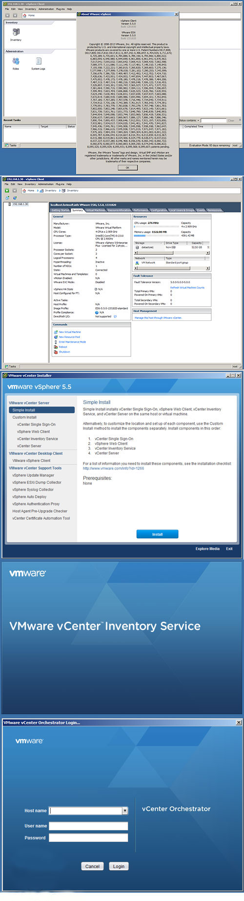
6.3 INSTALL VSPHERE
For information on the installation and configuration of vSphere, refer to the ESX and vCenter Server Installation Guide published by VMware.
Below are guidelines used for this environment when deploying the VMware View infrastructure.
Table 25) VMware View infrastructure components.
| VMware View Infrastructure Component |
Number |
| Virtual machine per vSphere server |
125 |
| Virtual machine per CPU core |
15.625 |
| Memory per Windows XP VMware View desktop |
512MB |
6.4 INSTALL VMWARE VCENTER SERVER
For information on the installation and configuration of VMware vCenter Server refer to the ESX and vCenter Server Installation Guide published by VMware.
To obtain licenses for VMware, contact your VMware sales representative.
6.5 CONFIGURE SERVICE CONSOLE FOR REDUNDANCY
Table 26) Configure service console for redundancy.
| Step |
Action |
| 1 |
Make sure that the primary Service Console vSwitch has two NICs assigned to it.Note: The network ports that the NICs use must exist on the administrative VLAN and be on separate switches to provide network redundancy. |
| 2 |
Open VMware vCenter. |
| 3 |
Select a vSphere host. |
| 4 |
In the right pane, select the Configuration tab. |
| Step |
Action |
|
Figure 33) VMware configuration. |
| 5 |
In the Hardware box under the Configuration tab, select Networking.Figure 34) VMware networking. |
| 6 |
In the Networking section, click the Properties section of vSwitch1.Figure 35) VMware networking properties. |
| 7 |
In the Properties section, click the Network Adapters tab.Figure 36) VMware vSwitch configuration. |
| Step |
Action |
|
|
| 8 |
Click Add at the bottom (pictured above) and select the vmnic that will act as the secondary NIC for the service console.Figure 37) Adding second vmnic to the vSwitch. |
| 9 |
Click Next (pictured above). At the following screen, verify and click Next, then at the following screen click Finish. At the following screen, click Close. |
| Step |
Action |
|
Figure 38) Adding second vmnic to the vSwitch confirmation.
Figure 39) Adding second vmnic to the vSwitch finish. |
| Step |
Action |
|
Figure 40) Adding second vmnic to the vSwitch close. |
6.6 CONFIGURE VMWARE KERNEL NFS PORT
Table 27) Configure VMware kernel NFS port.
| Step |
Action |
| 1 |
For each vSphere host, create a separate NFS VMkernel network in the existing virtual switch. The VMkernel will be setup on the private, nonrouteable NFS VLAN created in previous steps. This VLAN can be created on the either the separate VDC on the Nexus 7000 or on a private, nonrouteable VLAN using a vPC on the Nexus 5020 network. For this example, VLAN 350 is used.Note: Currently, VDC is not supported on Cisco Nexus 5000 switches. |
| 2 |
Use the following assignments for your NFS storage traffic VMware kernel IP addresses. Note: For the storage network the private subnet of 192.168.0.xxx is being used. |
| vSphere Host 1:192.168.0.11vSphere Host 2:192.168.0.12vSphere Host 3:192.168.0.13vSphere Host 4:192.168.0.14 |
vSphere Host 5:192.168.0.15vSphere Host 6:192.168.0.16vSphere Host 7:192.168.0.17vSphere Host 8:192.168.0.18 |
vSphere Host 9:192.168.0.19vSphere Host 10:192.168.0.20vSphere Host 11:192.168.0.21vSphere Host 12:192.168.0.22 |
vSphere Host 13:192.168.0.23vSphere Host 14:192.168.0.24vSphere Host 15:192.168.0.25vSphere Host16: 192.168.0.26 |
| 4. |
For the vSwitch for the NFS VMware kernel, set the load balancing policy to ―Route based on IP hash.‖ Figure 41) vSphere host NFS load balancing configuration. |
6.7 CONFIGURE VMOTION
Table 28) Configure VMotion.
| Step |
Action |
| 1 |
For each vSphere host, create a separate VMotion VMkernel network in the existing virtual switch. The VMkernel will be setup on the private, nonrouteable VMotion VLAN created in previous steps. For this example, VLAN 350 is used. |
| 2 |
Use the following assignments for your VMotion VMware kernel IP addresses. Note: For the storage network the private subnet of 192.168.1.xxx is being used. |
| vSphere Host 1:192.168.1.11vSphere Host 2:192.168.1.12vSphere Host 3:192.168.1.13vSphere Host 4:192.168.1.14 |
vSphere Host 5:192.168.1.15vSphere Host 6:192.168.1.16vSphere Host 7:192.168.1.17vSphere Host 8:192.168.1.18 |
vSphere Host 9:192.168.1.19vSphere Host 10:192.168.1.20vSphere Host 11:192.168.1.21vSphere Host 12:192.168.1.22 |
vSphere Host 13:192.168.1.23vSphere Host 14:192.168.1.24vSphere Host 15:192.168.1.25vSphere Host16: 192.168.1.26 |
6.8 VMWARE VSPHERE HOST NETWORK CONFIGURATION
Depicted below is the way a fully configured network environment will look once all the networking steps above have been completed.
Figure 42) VMware vSphere host configuration example.
6.9 ADD TEMPLATE VIRTUAL MACHINE DATASTORE TO VSPHERE HOST
Table 29) Add template virtual machine datastore to vSphere hosts.
| Step |
Action |
| 1 |
Open VMware vCenter. |
| 2 |
Select a vSphere host. |
| 3 |
In the right pane, select the Configuration tab. Figure 43) VMware configuration. |
| 4 |
In the Hardware box, select the Storage link. |
|
Figure 44) VMware virtual machine swap location. |
| 5 |
In the upper-right corner, click Add Storage to open the Add Storage Wizard.Figure 45) VMware Add Storage. |
| 6 |
Select the Network File System radio button and click Next.Figure 46) VMware Add Storage Wizard. |
| 7 |
Enter a name for the storage controller, export, and datastore (view_rcu_template), and then click Next. |
|
Figure 47) VMware Add Storage Wizard NFS configuration. |
| 8 |
Click Finish.Figure 48) VMware Add Storage Wizard finish. |
6.10 ADD VIEW_SWAP DATASTORE TO VSPHERE HOST
Table 30) Add vdi_swap datastore to vSphere hosts.
| Step |
Action |
| 1 |
Open vCenter. |
| 2 |
Select a VMware vSphere host. |
| 3 |
In the right pane, select the Configuration tab. |
| 4 |
In the Hardware box, select the Storage link. |
| 5 |
In the upper-right corner, click Add Storage to open the Add Storage Wizard. |
| 6 |
Select the Network File System radio button and click Next. |
| 7 |
Enter a name for the storage controller, export, and datastore (view_swap), then click Next. |
| 8 |
Click Finish. |
| 9 |
Repeat this procedure for all the vSphere hosts. |
6.11 CONFIGURE LOCATION OF VIRTUAL SWAPFILE DATASTORE
Table 31) Configure location of datastore virtual swap file.
| Step |
Action |
| 1 |
Open VMware vCenter. |
| 2 |
Select a vSphere host. |
| 3 |
In the right pane, select the Configuration tab. Figure 49) VMware configuration. |
| 4 |
In the Software box, select Virtual Machine Swapfile Location. Figure 50) VMware virtual machine swap location. |
| 5 |
In the right pane, select Edit. |
| 6 |
The virtual machine Swapfile Location Wizard will open. |
| 7 |
Click view_swap datastore and select OK. |
| 8 |
Repeat steps 2 through 7 for each vSphere host in the vSphere cluster. |
7 CONFIGURING THE ESX ENVIRONMENT WITH THE VSC
| Step |
Action |
| 1 |
Open VMware vCenter. |
| 2 |
Click on the NetApp tab found in VMware vCenter. Figure 51) NetApp tab. |
| 3 |
The Virtual Service Console (VSC) should now be visible. A screen similar to the image below should be visible. Figure 52) VSC configuration. |
| 4 |
Set the Recommended Values by right-clicking on the ESX host and selecting ―Set Recommended Values.‖ Figure 53) VSC configuration—set recommended values. |
| 5 |
The NetApp Recommended Settings screen should be visible. Leave the defaults checked and select OK. This will begin making the necessary changes to the ESX host. |
|
Figure 54) VSC configuration—NetApp recommended settings. |
| 6 |
Once the settings have been changed, the main VSC screen will be visible once again. The status will chance to ―Pending Reboot.‖ Figure 55) VSC configuration—recommended values set. |
| 7 |
Please reboot the ESX host to finish the configuration changes. |
8 SET UP VMWARE VIEW MANAGER 4.0 AND VMWARE VIEW COMPOSER
VMware View Manager is a key component of VMware View and is an enterprise-class desktop management solution that streamlines the management, provisioning, and deployment of virtual desktops. This product allows security for and configuration of the VMware View environment and allows an administrator to determine exactly which virtual machines a user may access.
View Composer is a component of the VMware View solution and uses VMware linked clone technology to rapidly create desktop images that share virtual disks with a master image to conserve disk space and streamline management.
For setup and configuration details for the different components of VMware View Manager and View Composer, refer to the VMware View Manager Administration Guide.
9 SET UP AND CONFIGURE WINDOWS XP GOLD IMAGE
9.1 CREATE A VIRTUAL MACHINE IN VMWARE VSPHERE
For the purposes of this portion of the document, follow whatever guidelines you have for both virtual machine size and RAM for your Windows XP virtual machine. For the purposes of this implementation we use 512MB RAM (VMware guidelines for RAM are between 256MB for low end and 512MB for high end). Follow the Guest Operating System Installation Guide by VMware, starting on page 145. Be sure to name this Windows XP virtual machine windows_xp_gold.
9.2 FORMAT THE VIRTUAL MACHINE WITH THE CORRECT STARTING PARTITION OFFSETS
To set up the starting offset using the fdisk command found in vSphere, follow the steps detailed below:
Table 32) Format a virtual machine with the correct starting offsets.
| Step |
Action |
| 1 |
Log in to the vSphere Service Console. |
| 2 |
CD to the virtual machine directory and view this directory by typing the following commands (shown below):cd /vmfs/volumes/vdi_gold /windows_xp_gold ls –lFigure 56) Using FDisk for setting offset—navigate to .vmdk directory. |
| 3 |
Get the number of cylinders from the vdisk descriptor by typing the following command (this number will be different depending on several factors involved with the creation of your .vmdk file):cat windows_xp_gold.vmdk Figure 57) Using FDisk for setting offset—find cylinders of the vDisk. |
| 4 |
Run fdisk on the windows_xp_gold-flat.vmdk file by typing the following command:fdisk ./windows_xp_gold-flat.vmdk |
|
Figure 58) Using FDisk for setting offset—starting FDisk. |
| 5 |
Set the number of cylinders. |
| 6 |
Type in x and then press Enter. |
| 7 |
Enter c and press Enter. |
| 8 |
Type in the number of cylinders that you found from doing step 3.Figure 59) Using FDisk for setting offset—set the number of cylinders. |
| 9 |
Type p at the Expert command screen to look at the partition table (which should be blank).Figure 60) Using FDisk for setting offset—set view partition information. |
| 10 |
Return to regular (nonextended) command mode by typing r at the prompt.Figure 61) Using FDisk for setting offset—set cylinder information. |
|
|
| 11 |
Create a new partition by typing n and then p when you are asked which type of partition. |
| 12 |
Enter 1 for the partition number, enter 1 for the first cylinder, and press Enter for the last cylinder question to make it use the default value. |
| 13 |
Go into extended mode to set the starting offset by typing x. |
| 14 |
Set the starting offset by typing b and pressing Enter, selecting 1 for the partition and pressing Enter, and entering 64 and pressing Enter. |
| 15 |
Check the partition table by typing p.Figure 62) Using FDisk for setting offset—view partition table to verify changes. |
| 16 |
Type r to return to the regular menu. |
| 17 |
To set the system type to HPFS/NTF, type t. |
| 18 |
For the Hex code, type 7.Figure 63) Using FDisk for setting offset—set system type and hex code. |
| 19 |
Save and write the partition by typing w. Ignore the warning, which is normal.Figure 64) Using FDisk for setting offset—save and write the partition. |
| 20 |
Start the virtual machine and run the Windows setup. Make sure to press Esc to bring up the boot menu and select ―CD ROM drive‖ to boot from CD. |
|
Figure 65) Using FDisk for setting offset—VMware boot screen.If you miss the boot menu, the VM may appear to hang with a black screen with only a blinking cursor. Press ctrl-alt-insert to reboot the VM and try again to catch the boot menu by pressing Escape. If you have trouble catching the boot process above, you can insert a boot delay in the VM settings. In the VI Client, right-click the VM, then à Edit Settings à Optionsà Advanced / Boot Options.Figure 66) Using FDisk for setting offset—advanced boot options.Note that boot delay is in milliseconds. You should return the boot delay to 0 after the VM boots normally from its virtual disk. |
| 21 |
When the installation gets to the partition screen, install on the existing partition. DO NOT DESTROY or RECREATE! C: should already be highlighted. Press Enter at this stage. |
- DOWNLOAD AND PREPARE THE LSI 53C1030 DRIVER
Table 33) Download and prepare LSI 53C1030 driver.
| Step |
Action |
| 1 |
Download the LSI 53C1030 driver from http://www.rtfm-ed.co.uk/downloads/lsilogic.zip. |
| 2 |
Using MagicISO or another third-party solution, create a .flp image containing LSI logic drivers. An alternative third-party solution is Virtual Floppy Drive 2.1. |
| 3 |
Using VMware vCenter 4.0 upload the file to the desired datastore by performing the following steps:a. At the Summary screen for a vSphere host, double-click the datastore icon to go into the Datastore Browser screen. |
9.4 WINDOWS XP PREINSTALLATION CHECKLIST
Table 34) Windows XP preinstallation checklist.
| Step |
Action |
| 1 |
Be sure to have a Windows XP CD or ISO image that is accessible from the virtual machine. |
| 2 |
Using the Virtual Infrastructure Client (VI Client), connect to VMware vCenter. |
| 3 |
Locate the virtual machine that was initially created and verify the following by right-clicking the virtual machine and selecting Edit Settings:a. A floppy drive is present.b. The floppy drive is configured to connect at power on.c. The device type is set to use a floppy image and is pointing to the LSI driver image.d. A CD/DVD drive is present and configured to connect at power on.e. A CD/DVD device type is configured to point at the Windows XP CD or ISO image. |
Figure 70) Verify virtual machine settings for virtual floppy drive.
Figure 71) Verify virtual machine settings for virtual floppy drive.
9.5 INSTALL AND CONFIGURE WINDOWS XP
INSTALL WINDOWS XP
Table 35) Install Windows XP.
| Step |
Action |
| 1 |
Using the virtual infrastructure client, connect to VMware vCenter Server. |
| 2 |
Right-click the virtual machine and select Open Console. This will allow you to send input and view the boot process. |
| 3 |
Power on the virtual machine created earlier by clicking the green arrow icon at the top of the console screen (shown below).. Figure 72) Power on button. |
| 4 |
As the Windows setup process begins, press F6 when prompted to add an additional SCSI driver. Specify the LSI logic driver on the floppy image (.flp) at this stage. |
| 5 |
Perform the installation of Windows XP as normal, selecting any specifics for your environment that need to be configured. |
| 6 |
Because this is a template, keep the installation as generic as possible. |
| 7 |
Enter a name for the storage appliance, export, and datastore (view_rcu_template), then click Next. |
| 8 |
Click Finish. |
CONFIGURE WINDOWS XP*
Table 36) Configure Windows XP.
| Step |
Action |
| 1 |
Install and configure the VMware tools. |
| 2 |
If not applied to the installation CD, install the most recent service pack and the most recent Microsoft® updates. |
| 3 |
Install the connection broker agent. |
| 4 |
Set the Windows screen saver to blank. |
| 5 |
Configure the default color setting for RDP by making the following change in the registry:HKEY_LOCAL_MACHINE\SYSTEM\CurrentControlSet\Control\Terminal Server\WinStations\RDP- Tcp – Change the color depth to 4 |
| 6 |
Disable unused hardware. |
| 7 |
Turn off theme enhancements. |
| 8 |
Adjust the system for best performance by going to My Computer>Properties>Advanced Tab>Performance Section>Settings. |
| 9 |
Set the blank screen saver to password protect on resume. |
| 10 |
Enable hardware acceleration by going toStart>Control Panel>Display>Settings Tab>Advanced Button>Troubleshooting Tab. |
| 11 |
Delete any hidden Windows update uninstalls. |
| 12 |
Disable indexing services by going to Start>Control Panel>Add Remove Windows Components>Indexing Service. |
|
Note: Indexing improves searches by cataloging files. For users who search a lot, indexing might be beneficial and should not be disabled. |
| 13 |
Disable indexing of the C: drive by opening My Computer, right-clicking C:, and selecting Properties. Uncheck the options shown below: Figure 73) Uncheck to disable Indexing Service on C: drive. |
| 14 |
Remove system restore points:Start>Control Panel>System>System Restore |
| 15 |
Disable any unwanted services. |
| 16 |
Run disk cleanup:My Computer>C: properties |
| 17 |
Run disk defrag:My Computer>C: properties>Tools |
*From Warren Ponder, Windows XP Deployment Guide (Palo Alto, CA: VMware, Inc., 2008), pp. 3–4.
DISABLING NTFS LAST ACCESS
Table 37) Disabling NTFS last access.
| Step |
Action |
| 1 |
Log in to the gold virtual machine. |
| 2 |
Open a CMD window by going to start > run, enter cmd, and press Enter. |
| 3 |
At the command line enter the following:fsutil behavior set disablelastaccess 1 |
CHANGE DISK TIMEOUT VALUE
Table 38) Change disk timeout values.
| Step |
Action |
| 1 |
Log in to the gold VM. |
| 2 |
Open a regedit by going to start > run, enter regedit, and press Enter. |
| 3 |
Find the TimeOutValue by following the path [HKEY_LOCAL_MACHINE\SYSTEM\CurrentControlSet\Services\Disk]. |
| 4 |
Change the key “TimeOutValue”=dword:00000190. |
| 5 |
Reboot the virtual machine now or at the end of the installation of applications and general system settings. |
INSTALL APPLICATIONS
Install all the necessary infrastructure and business applications in the gold VM. A few examples include VMware View Agent (if planning to use VMware View Manager) to allow specific users or groups RDP access to the virtual machines, MS Office, antivirus scanning agent, Adobe Reader, and so on.
INSTALL VMWARE VIEW AGENT
Install VMware View Agent (if planning to use VMware View Manager) to allow specific users or groups RDP access to the virtual desktops.
POWER OFF VM AND CONVERT TO TEMPLATE
After performing all the template customizations and software installations, power off the virtual machine because the customizations and installations need to be powered off to deploy. Then convert the VM to a template. This reduces the risk of accidentally powering on the VM.
10 RAPID DEPLOYMENT OF WINDOWS XP VIRTUAL MACHINES IN A VMWARE VIEW ENVIRONMENT USING RCU 3.0
For detailed installation and configuration instructions for RCU 3.0, please see the Rapid Cloning Utility 3.0 Installation and Administration Guide. NetApp highly recommends using RCU 3.0 because further steps in this guide will use RCU 3.0 to create datastores, deploy virtual machines, and configure datastores from vCenter.
CREATE CUSTOMIZATION SPECIFICATION
Create a customization specification for use with deployment of the VMs. The customization specification creates the information necessary for sysprep to successfully customize a guest OS from the VMware vCenter Server. It includes information on hostname, network configuration, license information, domain membership, and other information necessary to customize a guest OS. This procedure can be found in the vSphere Basic System Administration Guide on page 180. This customization specification can be used by RCU to personalize each VM. In addition to creating the customization specification, sysprep will need to be downloaded and installed. Procedures to do this can be found in the vSphere Basic System Administration Guide on page 325.
DEPLOY SPACE-EFFICIENT CLONES USING RCU 3.0
Using the template virtual machine as the source virtual machine, create the virtual machines using RCU 3.0 in four datastores (250 virtual machines per datastore) on storage controller A in vSphere Cluster A with eight vSphere hosts. These virtual machines will be imported into VMware View Manager as part of a manual desktop pool, in persistent access mode.
RCU will perform the following steps:
- Create the clones with file
- Clone the datastores with volume
- Mount the NFS datastores to the vSphere
- Create the virtual machines from the cloned
- Customize the virtual machines using the customization
- Power on the virtual
- Import virtual machines into VMware View
Table 39) Deploy space-efficient clones using RCU 3.0.
| Step |
Action |
| 1 |
Log into the VMware vCenter Server using the vCenter Client. |
| 2 |
Once storage controllers have been added, select the inventory button to get back to the servers and VMs. Right-click the VM to be cloned and select ―Create NetApp Rapid Clones.‖ Figure 74) RCU—Create rapid clones. |
| Step |
Action |
| 3 |
Choose the storage controller with the drop-down arrow and click Next.Figure 75) RCU—Select storage controller.Additionally, if the VMware VI client is not running, select Advanced Options and enter the password for the vCenter Server. |
| 4 |
Select the data center, cluster, or server to provision the VMs to and select ―Specify the virtual machine folder for the new clones‖ if necessary and select Next.Figure 76) RCU—Select data center, cluster, or server. |
| Step |
Action |
| 5 |
Select the disk format you would like to apply to the virtual machine clones and click Next.Figure 77) RCU—Select disk format. |
| 6 |
Enter in the number of clones, the clone name, the starting clone number, and the clone number increment. Then if guest customization is required, select the checkbox and the customization specification that will be applied after the VM has been provisioned. Then choose whether or not the virtual machine will be powered on after the clones are created. Then, if using VMware View, select ―Import into connection broker‖ and choose ―VMware View.‖ Then select Create new datastores if required and click Next.Figure 78) RCU—Specify details of the virtual machine clones. |
| Step |
Action |
| 7 |
If no datastores are present select Create NFS or VMFS datastore(s).Figure 79) RCU—Create and configure datastores |
| 8 |
Select the number of datastores to create. Then provide the root of the datastore name, the size of the datastore in GB, and the aggregate that you wish to use for the virtual machines. Then check the box for thin provisioning if needed. For NFS-based datastores the option to auto- grow the datastore will appear. You can then select the Grow increment size, the Maximum size, and whether or not you would like to provide specific datastore names. Then click Next.Figure 80) RCU— Create and configure datastores continued. |
| Step |
Action |
| 9 |
After datastore creation RCU will display the datastore that was created. If necessary you can create additional datastores at this time, then click Next.Figure 81) RCU— Create and configure datastores complete. |
| 10 |
Then select the datastore and click Next.Figure 82) RCU—Select the datastore. |
| Step |
Action |
| 11 |
If you selected ―Import into connection broker‖ the wizard will ask for the View Server hostname, the Domain name of the view server, the username, and the password. Then you can choose to create either an individual or a manual desktop pool and provide a new or existing pool name. For manual pools, the admin has the option of creating a persistent or a nonpersistent pool.After this has been completed click Next.Figure 83) RCU—Specify the details of the connection broker import. |
| Step |
Action |
| 12 |
Then review the configuration and if correct click Apply. The provisioning process will now begin. You can use the Tasks window within the vCenter Client to view the current tasks as well as the NetApp storage controller console.Figure 84) RCU—Apply configuration. |
| 13 |
After creating the virtual machines review the View Manager configuration and entitle users by logging into the VMware View Administrator 4 interface.Figure 85) RCU—Entitle users in VMware View. |
| Step |
Action |
| 14 |
Select the pool to be entitled—in this case it is the manual nonpersistent pool Helpdesk. Click Entitlements.Figure 86) RCU—Select the pool to be entitled in VMware View. |
| 15 |
Then on the Entitlements screen click Add.Figure 87) RCU—Open the entitlement screen in VMware View. |
| Step |
Action |
| 16 |
Select users or groups and either enter Name or Description to narrow down the search and click Find. Then click on the user(s) or group(s) to be entitled. Then click OK.Figure 88) RCU—Select users and groups in VMware View. |
| 17 |
Verify that the users and groups to be added are correct and click OK.Figure 89) RCU—Verify users and groups to be added in VMware View. |
| Step |
Action |
| 18 |
Verify that the pool is now Entitled and Enabled.Figure 90) RCU—Verify entitlement of pools in VMware View. |
| 19 |
Then adjust the pool settings by clicking on the pool and Edit and clicking Next until you get to the Desktop/Pool Settings. Then, after adjusting the pool to your liking, click Finish.Note: The settings in this example are for demonstration purposes only. Your individual settings may be different. Please consult the View Administration Guide for more information.Figure 91)RCU—Adjust pool settings in VMware View. |
| Step |
Action |
| 20 |
Test the connection by logging into a desktop using the View Client.Figure 92) RCU—Test the connection in VMware View |
Resize the FlexClone Volumes to the Estimated Size
Using RCU‘s datastore resizing feature, resize the four FlexClone volumes created on storage controller A to 525GB, planning for future growth considering the assumptions on new writes.
Note: The architecture proposed in this deployment guide balances the 2,000 virtual machines across 2 vSphere clusters with 8 vSphere hosts per cluster (16 vSphere hosts in total). The reason for this is that VMware does not support more than eight vSphere hosts per cluster when using VMware View Composer/linked clones. For further details, refer to View Composer Design Guide.
11 DEPLOY LINKED CLONES
This sample deployment has 500 virtual machines that are part of 2 automated desktop pools created using linked clones.
Pool 1: 500 virtual machines provisioned in persistent access mode with OS data disks and user data disk hosted on separate datastores created earlier.
Pool 2: 500 virtual machines provisioned in nonpersistent access mode with 1 datastore hosting OS data disk, created earlier.
For provisioning the linked clone–based desktop pools and associated virtual machines, refer to the procedure mentioned in VMware View Manager Administration Guide.
12 ENTITLE USERS/GROUPS TO DESKTOP POOLS
The next step is to entitle users/groups to the various desktop pools created in VMware View Manager. Follow the instructions in the VMware View Manager Administration Guide. Finally, install VMware View Client on every end user access device (PCs, thin clients, and so on).
13 SET UP FLEXSHARE (OPTIONAL)
FlexShare is a Data ONTAP® software feature that provides workload prioritization for a storage system. It prioritizes processing resources for key services when the system is under heavy load. FlexShare does not provide guarantees on the availability of resources or on how long particular operations will take to complete. FlexShare provides a priority mechanism to give preferential treatment to higher-priority tasks.
FlexShare provides storage systems with the following key features: Relative priority of different volumes
Per-volume user versus system priority
Per-volume cache policies
These features allow storage administrators to tune how the system should prioritize system resources in the event that the system is overloaded.
Since the configuration presented in this design guide uses a high water mark of 80% CPU utilization for each storage controller in a cluster, it may be necessary to enable critical VMs to be available in the event of a failover. NetApp recommends setting priorities for volumes that contain VMs that are especially critical and where potential downtime due to a storage controller failure could cause issues. By performing the following optional steps, critical VMs will not be affected by any performance degradation that could result in a storage controller takeover in the event of a failure.
Table 40) Enable priority settings.
| Step |
Action |
| 1 |
To enable priority settings, log into Storage Console. |
| 2 |
Enter the following command:3160-2> priority onWed Feb 3 11:16:32 EST [wafl.priority.enable:info]: Priority scheduling is being enabledPriority scheduler starting. |
| 3 |
To set the volume priority enter the following command:3160-2*> priority set volume <volume name> level=High system=High cache=keep |
| 4 |
To ensure the proper setttings have been made for the volume enter the following command:3160-2*> priority show volume -v veabugold Volume: veabugoldEnabled: on Level: HighSystem: High Cache: keepUser read limit: n/a Sys read limit: n/aNVLOG limit: n/a% |
14 TESTING AND VALIDATION OF THE VMWARE VIEW AND NETAPP STORAGE ENVIRONMENT
Below is a checklist designed to determine if your environment is setup correctly. Run these tests as appropriate for your environment and document the results.
Table 41) Testing and validation steps.
| Item |
Item Description |
| 1 |
Test Ethernet connectivity for VMware vSphere servers and NetApp. If using NIC teams or VIFs, pull network cables or down the interfaces and verify network functionality. |
| 2 |
If running in a cluster, test SAN multipathing by performing a cable pull or by disabling a switch port (if applicable). |
| 3 |
Verify that datastores are seen as cluster-wide resources by creating a custom map of the hosts and datastores and verifying connectivity. |
| 4 |
Test vCenter functionality for appropriate access control, authentication, and VI clients. |
| 5 |
Perform NetApp cluster failover testing for NAS and verify that datastores remain connected. |
| 6 |
Test performance and IOPs to determine that the environment is behaving as expected. |
15 100,000-SEAT STORAGE SCALE-OUT IN 10,000-SEAT INCREMENTS
Below is a chart detailing a FAS3160 HA pair storage scale-out from 10,000 to 100,000 seats. This chart uses the base deployment scenario detailed above in section 1.2. Because configurations are different in each environment the numbers may vary between different implementations. Therefore, the chart below represents this specific configuration and is to be used only as a reference and may not reflect each individual implementation.
Table 42) Incremental scale-out to 100,000 seats.
| # of Seats |
# HA Pairs |
# Disk Shelves |
# Servers |
# Nexus 5020‘s* |
| 10,000 |
2 |
8 |
80 |
4 |
| 20,000 |
3 |
15 |
160 |
6 |
| 30,000 |
5 |
22 |
240 |
7 |
| 40,000 |
6 |
30 |
320 |
9 |
| 50,000 |
8 |
37 |
400 |
11 |
| 60,000 |
10 |
45 |
480 |
12 |
| 70,000 |
11 |
53 |
560 |
14 |
| 80,000 |
13 |
60 |
640 |
18 |
| 90,000 |
15 |
68 |
720 |
19 |
| 100,000 |
16 |
76 |
800 |
21 |
*This configuration assumes two 6 port expansion slots have been added to the Nexus 5020
16 REFERENCES
TR-3705: NetApp and VMware VMware View Best Practices TR-3749: NetApp and VMware vSphere Storage Best Practices
TR-3505: NetApp Deduplication for FAS Deployment and Implementation Guide
TR-3747: NetApp Best Practices for File System Alignment in Virtual Environments ESX and vCenter Server Installation Guide
ESX Configuration Guide
vSphere Basic System Administration Guide Guest Operating System Installation Guide Getting Started With VMware View
VMware Infrastructure Documentation
Windows XP Deployment Guide
VMware View Manager Administration Guide
VMware View Reference Architecture Planning Guide
Cisco Nexus 7000 Series NX-OS Interfaces Configuration Guide, Release 4.1 Cisco Nexus 5000 Series Switch CLI Software Configuration Guide
17 ACKNOWLEDGEMENTS
The following people contributed to the creation and design of this guide: Vaughn Stewart, Technical Marketing Engineer, NetApp
Larry Touchette, Technical Marketing Engineer, NetApp
Eric Forgette, Software Engineer, NetApp George Costea, Software Engineer, NetApp Peter Learmonth, Reference Architect, NetApp David Klem, Reference Architect, NetApp
Wen Yu, Sr. Technical Alliance Manager, VMware
Fred Schimscheimer, Sr. Technical Marketing Manager, VMware
Ravi Venkat, Technical Marketing Engineer, Cisco
18 FEEDBACK
Send an e-mail to xdl-vgibutmevmtr@netapp.com with questions or comments concerning this document.
| VMware View on NetApp Deployment Guide |
|
19 VERSION HISTORY
Table 43) Version history.
| Version |
Date |
Document Version History |
| Version 1.0 |
May 2009 |
Original document |
| Version 2.0 |
February 2010 |
Updates to network configuration. RCU 3.0 and System Manager added. |
NetApp provides no representations or warranties regarding the accuracy, reliability, or serviceability of any information or recommendations provided in this publication, or with respect to any results that may be obtained by the use of the information or observance of any recommendations provided herein. The information in this document is distributed AS IS, and the use of this information or the implementation of any recommendations or techniques herein is a customer‘s responsibility and depends on the customer‘s ability to evaluate and integrate them into the customer‘s operational environment. This document and
the information contained herein may be used solely in connection with the NetApp products discussed in this document.


آخرین دیدگاهها